4 steps to quickly simulate your metal forming process
페이지 정보
작성일posted onLink
본문
4 steps to quickly simulate your metal forming process
Forgers are in a situation today that they must be right, the first time. That too with the least amount of time and money. This means a simulation software to check your metal forming process is inevitable. And what if the forging simulation software is very easy to learn and allows you to get started right away? Isn’t it ideal?
Keep reading.
The goal of this article is to show how easy it is to simulate your metal forming process in AFDEX. With only 4 pieces of information, you will be able to check the soundness of your process design. You can also check for the usual defects in forging process like folding, under fill or overlapping.
Let’s get started right away.
1. Geometry
The first and the most essential thing is the geometry of the dies and the dimensions of the initial work piece. AFDEX allows importing 2D and 3D geometries in dxf and stl formats respectively.
Simulate your process in 2D if your process is axisymmetric. Or if you can make a plane strain assumption. This could save you a lot of time. As 2D simulations are fast and closer to theory, you can change and optimize your process design. With ease and efficiency.
In a 2D multistage simulation, if you model the geometry as a single dxf file (as shown in Figure 1), it is very easy to automate the simulation. Figure 1 shows the three stage hot forging process of a hub bearing part. To simulate all the three stages of the process without any user intervention, position the workpiece on the left followed by the dies. Stage wise, from left to right. And if you position the dies in every stage as per the stroke values, you can avoid one more step in the simulation setup.
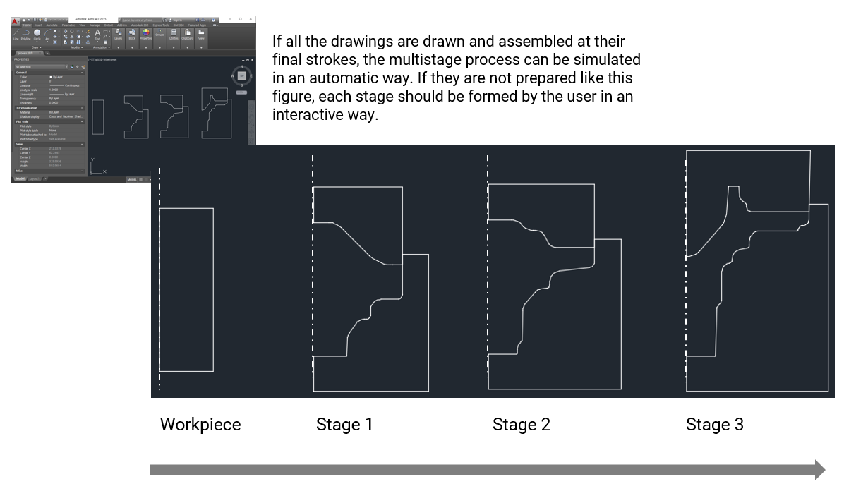
Figure 1: Modelling strategy for an efficient 2D simulation
For a 3D simulation, you must import the 3D stl geometries and then define individual stages and position them.
Bonus Tip:
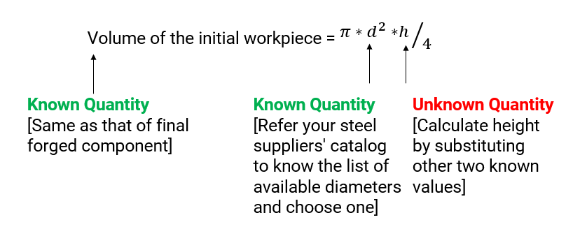
If you are not sure of the initial dimensions, don’t worry. Metal forming processes are constant volume deformation processes. Use this to your advantage. You can find the initial dimensions of the workpiece by knowing the volume of the final forged component. Follow the steps below.
a. Import the geometry of the final forged component in a CAD modelling software
b. Find the volume of this component (Almost every CAD modelling tool will have an option to show the volume)
c. Now refer your steel suppliers’ catalog and decide a initial billet diameter. You know the volume from Step b. So you can calculate the billet height.
Note: In hot forging, there is an option in AFDEX to account for the material expansion due to heat.
2. Material
Defining the material
behavior is very important for an accurate prediction of the metal forming
process. There are three ways to define a material in AFDEX.
1. Select the material from the inbuilt database of AFDEX.
A lot of popular material grades are available for direct selection. This is the easiest method, used by majority of our users.
[or]
2. Use constitutive equations like Hollomon’s equation or Johnson Cook Material Model
Using this method requires a sense of engineering judgement. Every metal forming process is unique and there is no "one-equation-fits-all" constitutive equation. So exercise caution while using this method. Refer literature or carry out experiments to estimate the constants in these constitutive equations. Mistakes in material constants lead to very high computational time or inaccurate predictions.
[or]
3. Use AFDEX_MAT to generate flow stress curves from experimental data
What if you have carried out tensile or compression tests and have the load vs. elongation data? Or your material supplier has given you only this? No worries. You can use AFDEX_MAT to convert this information into flow stress curves for the simulation.
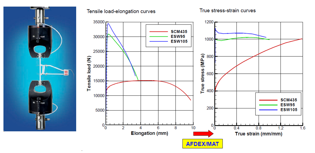
Figure 2. Material Identification using AFDEX MAT [1] [2]
To know how this method works, refer the links below.
http://msjoun.gnu.ac.kr/pub/paper/2008/paper-3.pdf
http://msjoun.gnu.ac.kr/pub/paper/2008/paper-24.pdf
To apply this method in AFDEX, refer tutorials 2D Part 2 > Ex 08 and Ex 09 inside your AFDEX installation folder.
3. Press
The third thing you need for simulating a metal forming process is the details of the press machine. In the case of rate-independent material definition (constitutive equation), especially for cold forging processes, considering unit velocity (1 mm/s) for the press is a good assumption.
In other cases, define the press information based on the specifications of the press that you use in your shop floor. It could be a crank press or mechanical press or a hammer forging press. It is also possible that you might be having the velocity profile of the dies with respect to time as shown in Figure 3. This is also an option for the forgers to define the press behavior in a metal forming simulation.
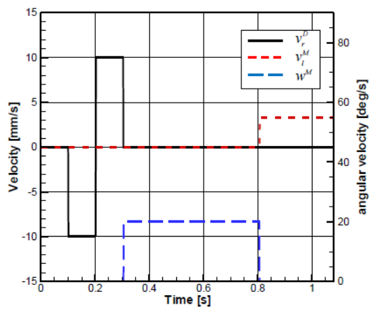
Figure 3. Velocities of workpiece and dies with respect to time [6]
(Blue – Workpiece, Black – Dies, Red – Mandrel)
4. Friction
Friction is one among the important factors influencing the outcome of a Finite Element Analysis (FEA) of a forging process. The friction between the dies and the workpiece is usually formulated using Coulomb friction model, constant shear friction model or a hybrid friction model which combines the Coulomb and constant shear friction model.
When you are deciding on the values used to define these formulations, a sense of engineering judgement is usually advocated. You can also refer standard literature and find out the friction formulation used for the process of your interest.
There are standardized tests like ring compression tests (Figure 4) that facilitate the calculation of the friction coefficients which can be directly used in metal forming simulations. By measuring the change in the diameter of a specimen (hollow cylinder) with respect to its reduction in the height, the ring compression test quantifies the magnitude of the friction coefficient that exists between the workpiece and dies. If you are interested to know more about the effect of friction laws in metal forming processes, check these links [4] and [5].
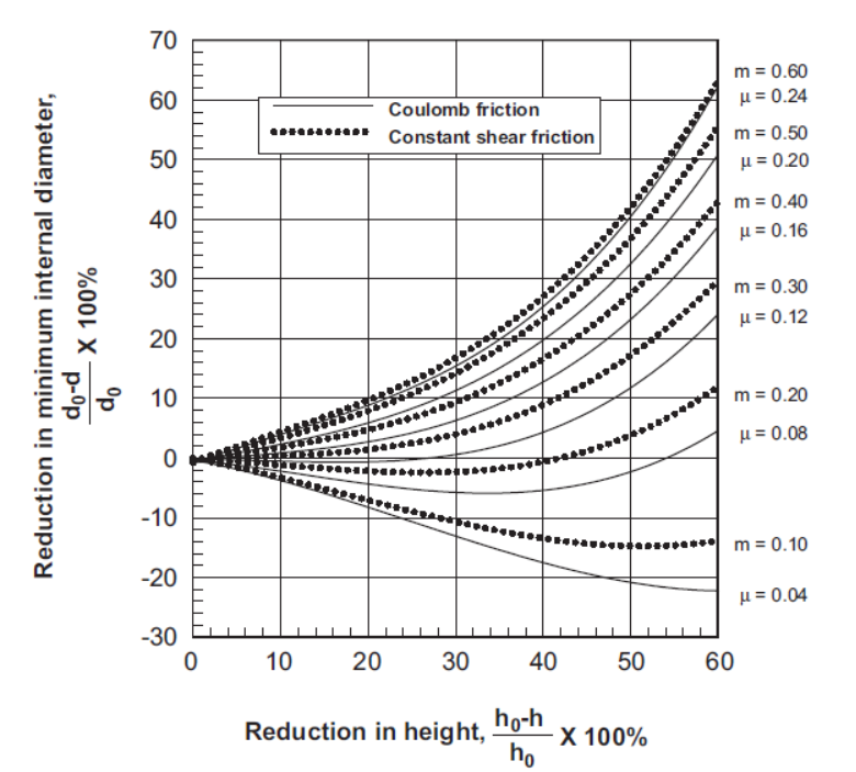
Figure 4: Friction
evaluation curves for a material at the elevated temperature, obtained by ring
compression simulation [4]
So with just these four pieces of information – Geometry, Material, Press and Friction – you can simulate and optimize your metal forming process design in AFDEX.
You can also see how this process is simulated in AFDEX by clicking on the link below.
https://www.youtube.com/watch?v=jPlh-gxtXxM
Do you want to look at an example?
2D - https://www.youtube.com/watch?v=Nmvsp19lfSU
3D - https://www.youtube.com/watch?v=1VISp3gGwS8
We hope this article was informative. With just the four steps explained above, you can easily simulate your manufacturing process using AFDEX. Do you have an existing process design for your metal forming process that you want to check or optimize? We can help. Please write an email to [email protected]. We can also give you a trial version if you are interested.
If you like this article, please do share it with your friends and coworkers. Thank you.
References:
[1] Materials Science and Engineering: An Introduction
[2] http://msjoun.gnu.ac.kr/pub/paper/2008/paper-3.pdf
[3] http://msjoun.gnu.ac.kr/pub/paper/2008/paper-24.pdf
[4] https://www.afdex.com/archive/blog/18