Metal forming simulation with emphasis on metal flow lines
페이지 정보
작성일posted onLink
본문
Metal forming simulation with emphasis on metal flow lines
There
are so many kinds of failures occurring in developing metal forming processes,
which are very costly and time-consuming. Under-filling or overlapping defects
can be easily removed using the MFS technologies. In many real situations, in
fact, those defects can be removed based on the experiences (1).
However, metal flow line defects are very difficult to be removed empirically and most power transmission parts have their own optimal metal flow lines. Metal flow lines are basically formed during manufacturing of the rolled, drawn, or extruded bars which are employed for the billets for metal forming. Fig. 1(a) shows the metal flow lines in extrusion. It is noted that the non-extruded part of the material in this figure also has metal flow lines, which indicates that they are not formed newly but their patterns are changed during extrusion or forging.
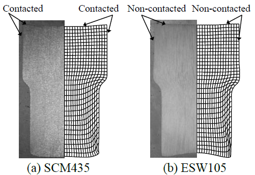
Figure 1 compares the predictions with experiments of an axi-symmetric cold forward extrusion process with two different materials of SCM435 and ESW105(2). It should be noted that the material ESW105 is a pre-heat-treated special steel and that even the heat-treatment before the extrusion cannot erase or change the metal flow lines. It can be seen that the predicted and experimental ends of the extrusions are very close to each other for the two materials and that the predicted and experimental corners in the punch sides are also similar.
Apparently, metal flow lines have strong relationship with the structural strength. However, the research on finding the optimized metal flow lines have been very rare in spite of its importance. In fact, many process design engineers and many mechanical parts design engineers are in lack of the quantitative evidences on the optimized metal flow lines. Thus, a more systematic approach to optimize the metal flow lines based on experiments and predictions are still strongly needed.
In this article, the effect of metal flow lines on structural rigidity is discussed and the importance of process design techniques considering the sound metal flow lines is emphasized with some applications. Joun et al (2). presented the detailed metal flow lines for 2D application with the highest accuracy. Recently they also presented a new function of three-dimensional visualization of metal flow lines as shown in Fig. 2.
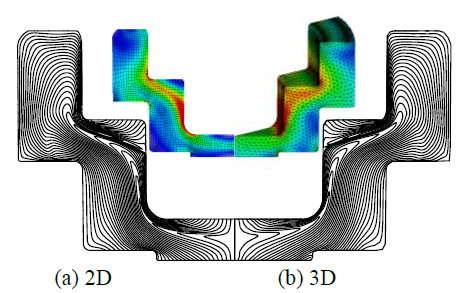
Figure 2: Comparison of metal flow lines obtained by 2D and 3D
simulations
Fig. 2
compares the metal flow lines obtained by 2D and 3D approaches. It should be
noted that there must be some difference between them due to the difference in
the theoretical backgrounds. It is apparent that 2D predictions are closer to
the theory of plasticity because some approximation in 3D calculation is
inevitable. It is, however, noted that the difference can be negligible from
the standpoint of engineering.
Process designs considering metal flow lines
a. Weak strength due to bad metal flow lines
Two different axisymmetric three-stage hot forging processes for outer race of a constant velocity joint produced quite different metal flow lines as shown in Fig. 3. Of course, this difference in metal flow lines also caused so much different effective strain distribution shown in Fig. 4. The difference was due only to the difference of die shapes of the second stage.
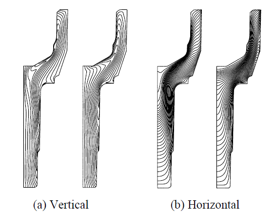
Figure 3: Two metal flow lines for two different process designs
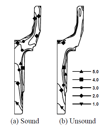
Figure 4: Effective strain distribution
b. b. Non-symmetric
metal flow defect
Some parts have the planes of symmetry in both geometry and mechanics in their service. In this case, their optimal designs should meet the symmetric requirements on the mechanical properties. For example, particularly when the symmetric parts are exposed to attrition, the metal flow lines should be symmetric. Otherwise, the premature fracture or small wear life at the weak side may happen even though the strong side still remains safe.
A typical example was found from a hub-bearing manufacturer (4). Fig. 5 compares experimental and predicted metal flow lines generated by automatic three-stage hot forging of bearing parts. It is noteworthy that this example is a typical case of failed process design due to non-symmetric and unsound metal flow lines in spite of the sound surface quality of the forging, particularly emphasizing the importance of MFS.
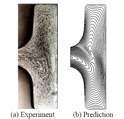
Figure 5. Comparison of metal flow lines
Concluding remarks:
MFS has become essential in developing a metal forming process. Owing to advances in computer hardware technologies, the major problem has already shifted from academic sides to application sides. The consumers often request the manufacturers to employ the technology and the frequency will increase. Nowadays application of metal forming simulators became essential especially for automobile industry.
One of the most important roles of the metal forming simulation technologies is to make it possible to obtain the optimized metal flow lines which cannot be achieved without this technology. In this paper, the metal flow lines in product design and its metal forming process design are emphasized with typical application examples, revealing that the metal flow lines have great influence on the structural rigidity of the product.
References:
[1]
Joun, M. S., Lee. M. C., Eom, J. G., “Intelligent metal forming simulation,”
Proceeding of ASME MSEC2011-50128, 2011.
[2]
Joun. M. S., Lee. S. W., Jung. J. G., “Finite element analysis of a multi-stage
axisymmetric forging process having a spring-attached die for controlling metal
flow lines,” Int. J. Mach. Tools Manuf., Vol. 38, No. 7, pp. 843~854, 1998.
[3]
Joun. M. S., Eom. J. G., Lee. M. C., Park. J. H., Yoon. D. J., “Tensile test
based material identification program AFDEX/MAT and its application to two new
pre-heat treated steels and a conventional Cr-Mo steel,” International Journal
Of Modern Physics B, Vol. 22, No. 31~32, pp. 5774~5779, 2008.
[4
Joun. M. S., Moon. H. K., Shivpuri. R., “Automatic simulation of a sequence of
hot-former forging processes by a rigid-thermoviscoplastic finite element
method,” Journal of Engineering Materials and Technology, ASME, Vol. 120, No.
4, pp. 291~296, 1998.
Do follow us on LinkedIn to
stay updated and know more interesting simulation examples from a wide variety
of metal forming processes.